Legacy radio going FASST (2.4ghz), Part 1
A simple 555 timer based interface
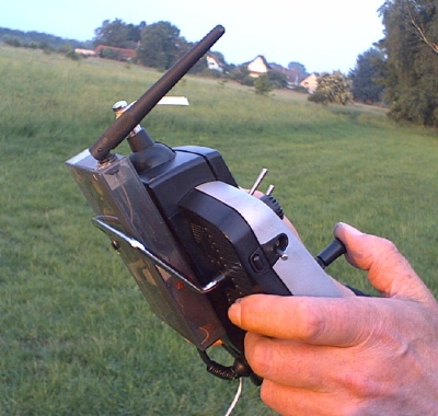
I have managed to attach the Futaba T6EXP 2.4 GHz transmitter to the buddy connector of my Multiplex Royal Evo 12. The 2.4 GHz box transmits seven channels. It works flawlessly and fully transparent as the Evo's transmitter modul.
Meanwhile, I have also made an adapter for my son's Multiplex Cockpit SX, using an ATtiny microcontroller. See 'Legacy radio going FASST, Part 2: A microcontroller based interface'.
I am not recommending this modification to anybody. I am only reporting what I did and how. Because of the high risk a transmitter shut down could cause, the adapter circuit should be built and used only by people who have sufficient skills in building electronic devices. If you wish to do so you do it at your own risk.
What I did is mainly based on Rudy Fiala's findings. He has also pointed to the fact that Futaba's R606FS actually is a 7-channel-receiver - with only one connection missing.
It took three steps to get the 7 channel 2.4ghz FASST Evo running with the R606FS:
First, the receiver: I have added the small 220R resistor, which is missing at the 7th channel's signal lead. See picture. If you do not need seven channels, you can use the R606 as it is, of course. The T6 adapter works as well with the R607FS or the R617FS, which have that missing resistor ex factory.
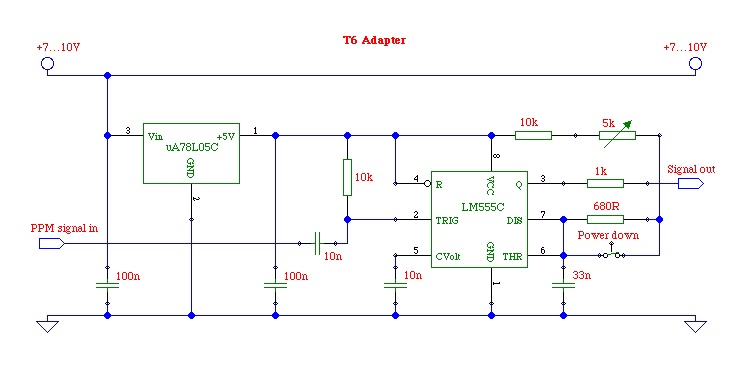
Second, the transmitter: It sits piggy-packed on a somewhat larger board, which carries the LEDs, the buddy connector, and the 5V voltage regulator. If you look at the solder side of this board, you will see four leads connected on the left and three leads on the right side of the board. The four leads on the left are for the buddy connector only, so I removed them. The three leads on the right carry ground, battery plus, and the PPM signal. The signal package is a usual 22.5 ms frame with the servo pulses starting with a high pulse at 3.3V. The TX module can be adapted to almost any standard PPM signal train carrying up to 8 servo channels by means of a pulse forming circuit like this:
Third, adapting the Evo's buddy connector: Pin 4 carries the PPM signal package, the start pulses are low, the high level voltage is the same as the battery voltage. The supply voltage comes from pin 2 of the buddy connector. Pin 3 is connected to battery minus or ground. You have to bridge pins 5 and 3 in order to switch the Evo's Hf transmitter off and have the signal routed to pin 4. Other radios, of course, do have different connections.
The adapter circuit that has been checked against a number of transmitters (i.e. Multiplex Royal Evo, 3030, 4000, Graupner MC-22). The input signal is the PPM data stream that is available at the buddy connector. Signal polarity does not matter, but the signal amplitude must be at least 3.3V peak-to-peak. Supply voltage (7 ... 25V) can as well be drawn from the buddy connector and is passed through to the T6 TX module, which has its own 5V-regulator. With the Power down switch open, the TX module is running in low power mode for range checking. You must not use that mode in regular operation.
The adapter forms a PPM data stream with positive start pulses appropriate for the FASST module. Different pulse widths switch the TX module to different modes. Originally, in the T6EXP, only the width of the first pulse is altered for the different modes, but is seems to make no difference for the TX module if all pulse widths are changed uniformly. These are the pulse widths and the respective modes as published by Stephan on the German RCLine board:
400 microseconds: regular transmission without failsafeThe circuits requires trimming at the initial start-up. With the switch open I adjust the trimmer so that the module switches to power down mode (green LED on, red LED blinking). Then, by closing the switch, it goes to regular transmission including failsafe (green LED on, red LED off). With the Evo, I am using channel 3 as the motor channel, since the R606, R607 and R617 receivers feature a failsafe function only for that channel. The motor off failsafe position is transmitted on channel 8. I have adjusted channel 8 to a fixed value of -100%.
'Legacy radio going FASST, Part 2: A microcontroller based interface'.